The master branch has just been updated! It now includes a major new tool, called the MaterialTool. This is a dedicated app for building materials and applying them to objects, and includes some cool new features…
In XLE, most material information can be authored in standard graphics packages (like 3DS Max, Maya, Substance Painter, etc). In particular, the most critical material values (color, roughness, specular & metal) can come directly from standard packages.
But in cases we want to add custom information to models, or even develop custom shaders for complex materials. This is were the MaterialTool comes in. There is some functionality in common with the ModelViewer and LevelEditor tools – but the MaterialTool provides a convenient focused tool for this kind of work.
Basic functionality
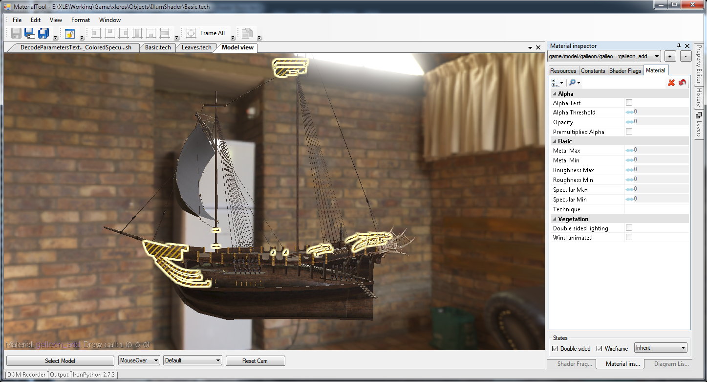
Our core functionality allows us to preview a model (much like the ModelViewer, with various rendering modes), click on materials and then change their properties (such as opacity, translucency modes, and various shader flags).
This works within the Sony ATF framework, and so we have all of the handy features from the LevelEditor, such as:
- detachable, arrangeable windows
- IronPython scripting and cvar access
- interface skinning, keyboard rebinding, etc…
- and, of course, it’s all very extensible C# code, convenient for adding custom features
Node Diagram editor
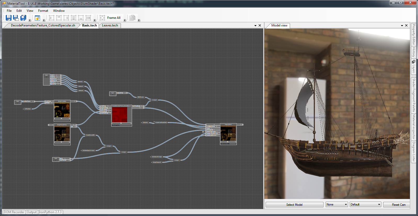
Also integrated is a new version of the node diagram editor. This is used for building custom shaders for special cases. Make it possible to visually create shader logic. It’s designed for use by both programmers and technical artists.
Each diagram becomes a expression in HLSL shader code (and this can be used, just like any other shader). But these expressions can become very complex, and can (indirectly) include loops and conditions.
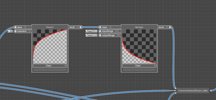
Each node in the diagram has a real time preview. For mathematical nodes, this might be a chart.
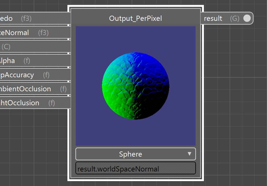
But we can also have 3D previews (using a sphere, box or a full model).
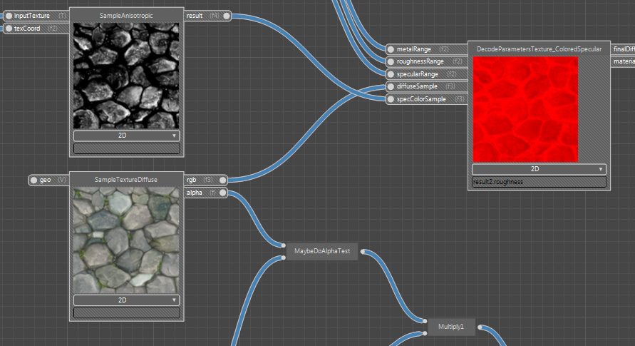
Texture nodes can also be previewed using a flat 2D preview.
Previewing the diagram at every node makes the process of creating shaders much more visual. The effect of each function on the final shader becomes immediately apparent.
For example, XLE has some shader code for converting a “specular color” texture into the new “roughness, specular, metal” scheme (for convenience reasons). Building this logic as a node diagram is infinitely easier than just working in raw HLSL directly, because we can see the results immediately, and in detail.
Nodes are HLSL functions!
So far, the node diagram tool sounds fairly standard. But there’s an important twist. A node diagram is just a collection of “nodes” that have been connected together. But where do those nodes come from, and what do they do?
XLE contains a permissive HLSL parser (written in Antlr3). This parser can parse almost all valid HLSL code and can build an abstract syntax tree of it’s contents. In particular, we can use this parser to extract the function signatures from a shader file.
So, for example the shader file Surface.h contains the functions VSIn_GetLocalPosition, VSIn_GetLocalTangent, etc… Our parser can read Surface.h and find those functions, plus their parameters, output type, semantics, etc.
So, there’s our answer! Our nodes are actually HLSL functions. And since our parser works will every shader source file in XLE, that means that any shader function can be used as a node.
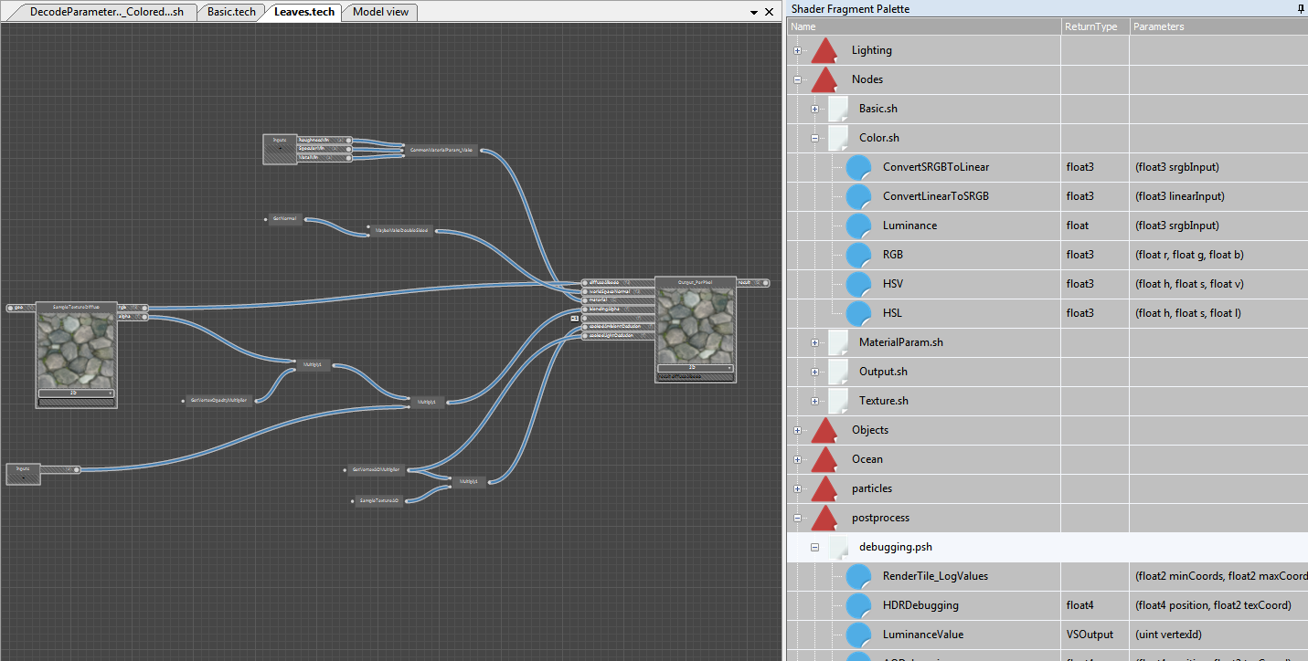
Nodes are dragged into the diagram from something called the shader fragment palette.
There are no hard coded nodes, and the shader fragment palette is reloaded on the fly. So, if you’re building a diagram and suddenly realize you want a new node type… Just open a text editor, add a new function into a shader file, and it can immediately be dragged into your diagram.
The xleres/Nodes directory is set aside to contain functions that are specifically intended to be used as nodes. In some cases, functions in this folder are just thin wrappers over other functions. But it’s recommended to mostly use functions from this directory in node diagrams, so as to isolate diagrams from shader changes.
Each diagram is both a node type and a shader function
Use of HLSL as nodes creates some interesting advantages. Each diagram itself is a shader function. And so, when you save a diagram to disk, you can then use that diagram as a node in another diagram. In this way, we can have embedded diagrams very easily.
It also means that we have full control over when to use a diagram, and when to use text-based HLSL. Some expressions are just awkward to do in diagram form.
For example, try implementing a Modulo function as a diagram using just divide, multiply, subtract and round nodes. It can be done, but it’s awkward. In cases like this, it’s better to just write a text based function (in this case, using built-in shader language functions) and then use that function within your diagram.
Complex shaders
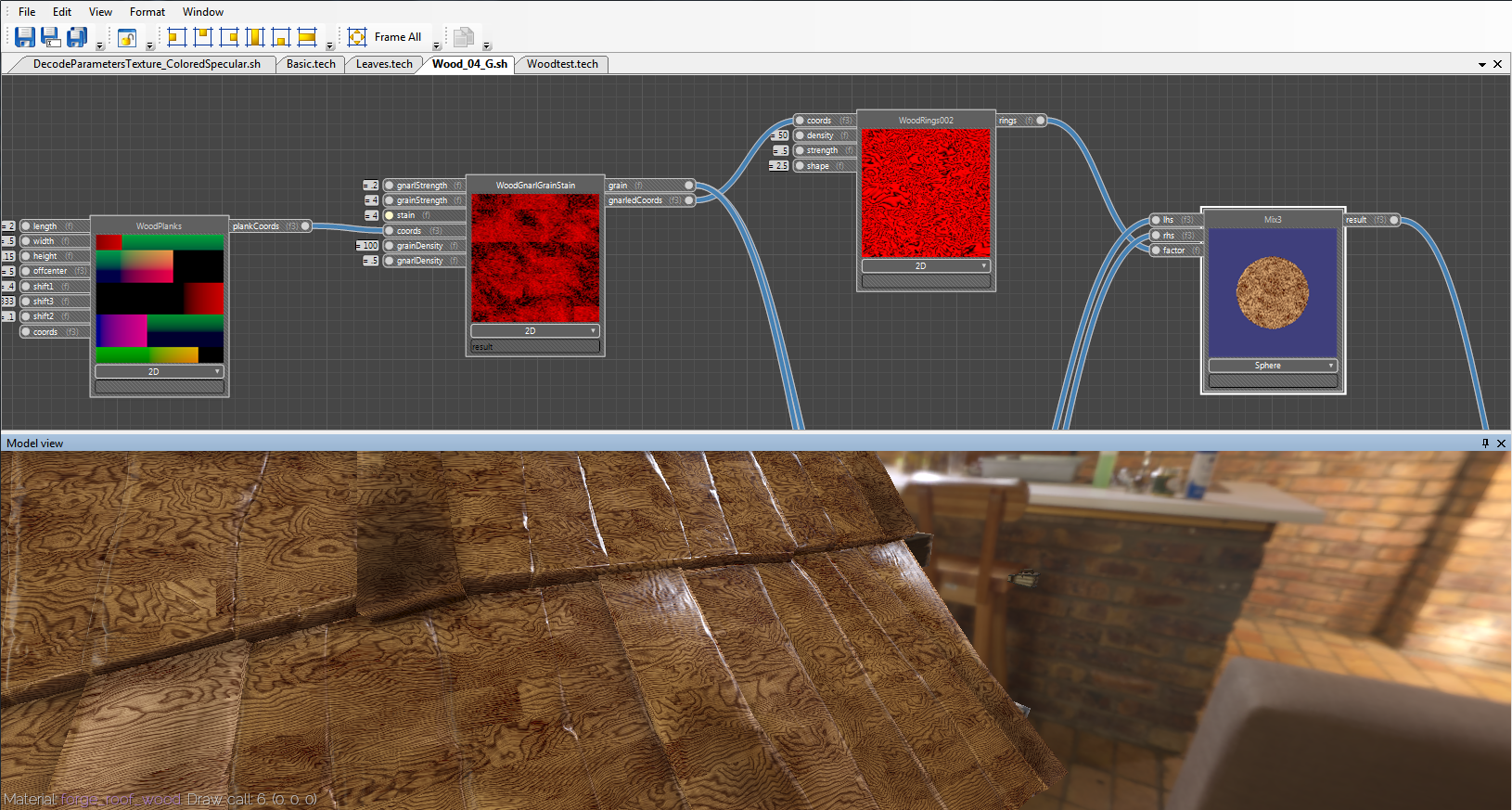
These methods can be used to create arbitrarily complex shaders. Above is an example of a node diagram that was duplicated from the (CC-Zero) Cycles Material Library: http://www.blendswap.com/blends/view/56470
This is a 100% procedural texture, with no texture inputs. The XLE implementation uses the same arrangements of nodes and the same constants to give the same final results as the Cycles render engine.
Since the output is text HLSL code, the normal HLSL compiler and optimizers apply. There are certain cases in which hand written HLSL code will be more efficient the diagram based stuff – but that might be an advanced topic. In many cases, the diagram based shaders should be as efficient as hand written code.
Using a diagram as a material
To use a diagram as an object material, follow these steps:
- Create an output node from Nodes/Outputs.sh:Output_PerPixel
- You may need some inputs from geometry, these are usually “Get” or “Sample” functions. For example, Nodes/Texture.sh:SampleTextureDiffuse, and Surface.h:GetNormal
- To create a material parameter, right click in empty space and select “Create Input”
- Go to Edit/Diagram Settings…
- Select “Technique (material for any object)” as the diagram type
- Save your diagram! (you must save to see the results in the Model view window currently)
- Now you can go to the “Model view” window, right click an object and select “Assign Technique (…)"
Check out Working/Game/xleres/Objects/Basic.tech as a starting example.
Node graph dynamic linking
You may notice some similarity between this technology and a previous post – Dynamic Function Linking Graph for Shaders. They are similar because they both involve linking together the inputs and outputs of shader functions. But unfortunately they don’t work together yet… Perhaps later…?
Other uses of the HLSL parser
The HLSL parser has some other cool applications… It can parse most valid HLSL code. And actually, it’s fairly permissive, so some invalid HLSL code will parse, as well.
I’ve been using this parser as a linter for HLSL code in the Atom editor! There is a linter plugin for Atom, and so all it involved was creating a script that ran the “ShaderScan” sample. This reads HLSL code and spits out parsing errors.
And so, those parsing errors now appear in real time while writing HLSL code in Atom. This has two uses for me, currently… It catches certain errors in the HLSL (Intellisense-style). But it’s also serving as a way to test the parser itself!
In theory, this parser could also be extended to provide automatic conversion between HLSL and GLSL (or other languages). Some engines use this kind of approach for dealing with cross platform issues. Another possibility is just to use a complex series of #defines… But either method would be awkward in it’s own unique way.
Support for other languages
Currently the node diagram tool is designed for use with HLSL. However, in theory it can also be used with other languages. All we need is a parser that can extract the function signatures. Since HLSL is a fairly generic c-like syntax, it shares a lot of similarity with many other languages. So the code that builds HLSL from the shader diagram could probably be easily adapted for languages (like Lua, Python, D, Swift, whatever).
This could be handy because HLSL is tied to GPU execution only. But another language would open the door for CPU side execution – which could be used for game logic, physics or any other systems. This would be handy, because it would mean reusing the same core node diagram functionality for multiple separate tasks.
